SMM isolation - SMI deprivileging (ISRD)
This two-post series details the inner workings of System Management Mode (SMM) isolation on the Intel platform and interaction with Windows.
This post focuses on SMI deprivileging. For security policy reporting and interaction with Windows, see the next post.
Table of contents👇
Goals
The goal of this series is to shed light on the designs and implementations of two of Intel’s “below-OS” security features: Intel System Resources Defense (ISRD) and Intel System Security Report (ISSR), for security researchers and system software designers.
The readers are assumed to be familiar with the concept of SMM isolation. If not, I suggest reading the following articles and whitepapers published by Intel and Microsoft:
- Intel® Hardware Shield: Trustworthy SMM on the Intel vPro® Platform
- System Management Mode deep dive: How SMM isolation hardens the platform
- Optionally:
While these explain background problems and the architecture of the solutions very well, implementation details are not the focus of the publications. Even beyond these whitepapers and articles, very little information on their implementation exists publicly. Thus, it is worth detailing these for security minded folks.
This article is based on the results of reverse engineering the 12th gen system (Dell Latitude 7330 with BIOS version 1.18.0) and likely has incorrect analysis. Please message me if you find misinformation.
Overview of ISRD
Intel System Resources Defense (ISRD), code-named “Devil’s Gate Rock”, is the Intel implementation of SMM isolation. Under this architecture, SMM code is placed in user-mode except very small pieces provided by Intel, thereby minimizing the impact of vulnerabilities in SMM interrupt (SMI) handlers.
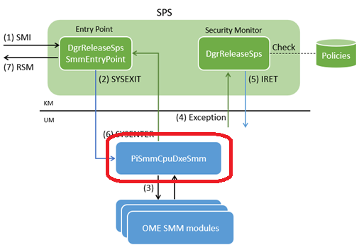
The below diagram illustrates the SMM execution flow in this architecture.
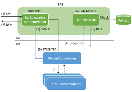
At the high level, SMIs are handled as follows:
- On SMI, the SMM entry point in kernel-mode gets executed.
- The SMM entry point jumps to user-mode.
- One of the OEM-developed SMM modules gets executed to handle the given SMI.
- When the SMM module attempts to access system resources, an exception occurs.
- The security monitor handles the exception according to the security policies.
- The security monitor returns to user-mode.
- Repeat (4) and (5) as necessary.
- When the SMI is handled, execution returns to kernel-mode code.
- Kernel-mode code exits SMM.
Notice that only the SMM entry point and exception handling code are executed in kernel-mode, compared with traditional SMI handling where all code runs in kernel-mode.
Core implementation
Let us look at the installation and execution flow of ISRD core components in more detail.
The policy installation and updates are explained in the Policy management implementation section.
SMM Policy Shim
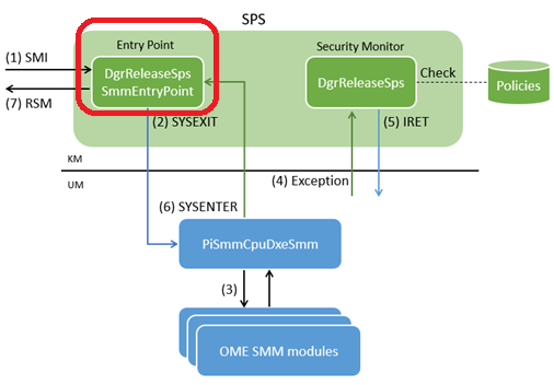
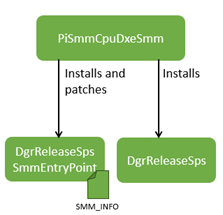
SMM Policy Shim (SPS) is kernel-mode SMM component provided by Intel to OMEs as blob files. It consists of two files: DgrReleaseSpsSmmEntryPoint and DgrReleaseSps.
DgrReleaseSpsSmmEntryPoint
- GUID:
7C7D635B-8B9C-463C-9F7F-91F60906848F - Developer: Intel
This is a raw blob file whose offset zero is the SMM entry point code in real-mode.
This code sets up and switches to long-mode, locks security sensitive registers with the SMM_SUPOVR_STATE_LOCK MSR (*1), and jumps to a user-mode entry point by executing the SYSEXIT instruction if ISRD is enabled (*2).
Since the SMM entry point code is security critical and needs to be as simple as possible, when it is installed on SMM memory (SMRAM), the code is patched to accommodate non-constant values instead of having complex logic to compute and/or resolve them within the SMM entry point code. This patching is done by PiSmmCpuDxeSmm walking through the SMM_INFO structure at the end of this file. The structure contains the entries with the following format, instructing PiSmmCpuDxeSmm which addresses to patch.
struct SMM_INFO_ENTRY {
  uint8_t Type;
  uint8_t SizeInBytes;
  uint16_t Offset;
};
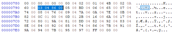
As such, some code is incomplete on disk. As an example, this is code on disk that lacks a proper value for CR3.
00000085: B8 00 00 00 00  mov eax, 0
0000008A: 0F 22 D8        mov cr3, rax
However, 03 04 86 00 in the patch entries below lets PiSmmCpuDxeSmm fill in the CR3 value (type 03) by patching a 04-byte patch at the offset 0086 at runtime. This approach reduces the complexity of the entry point code. For the list of the patch entries, see the Appendix section.
Finally, this file also implements a function that runs when execution returns from user-mode with the SYSENTER instruction. This function executes the RSM instruction at the end, exiting SMM.
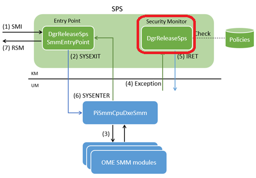
DgrReleaseSps
- GUID:
7134E3EE-7FA6-4489-87A7-AE38984EAED8 - Developer: Intel
This is the cornerstone of the ISRD architecture – the security monitor implementing part of policy enforcement for user-mode SMM modules.
This module implements interrupt handlers, and in the case of #GP from user-mode, it evaluates a cause and a security policy. If the security policy allows the operation, this module performs the action that caused the exception on behalf of user-mode and returns the result.
For instance, when a user-mode SMM module executes the RDMSR instruction, it causes #GP. The exception is handled by this module. The module determines that the instruction is to read MSR_SMM_FEATURE_CONTROL by decoding bytes at user-mode RIP. Then, it looks up the security policy, finds that this particular MSR is allowed to read, executes the RDMSR instruction for the same MSR, updates user-mode EDX:EAX and RIP accordingly, and returns to user-mode.
In case an exception is caused by an action not allowed by the security policy, or is anything other than #GP from user-mode, it halts processor execution (*3).
Note that some operations from user-mode are always allowed and handled without consulting the security policy. The below table summarizes how user-mode operations are handled:
| Operation | Allowed | Enforced by |
|---|---|---|
| Read from and write to MSRs | By policy | SPS |
| Read from and write to IO ports | By policy | Processor |
| Write to debug registers | By policy | SPS |
| Read from debug registers | Always | SPS |
| Read from CR2 | Always | SPS |
cli (*4) |
Always | SPS |
wbinvd |
Always | SPS |
For IO ports handling, we will take a closer look in the PpamPlatformSmm section later. The later Policy management implementation section describes how policies are installed and customized.
PiSmmCpuDxeSmm
- GUID:
A3FF0EF5-0C28-42F5-B544-8C7DE1E80014 - Developer: TianoCore, customized by OEM
This module is an installer and glue.
During the SMM configuration phase, this component detects the compatibility with ISRD through MSR_PLATFORM_INFO (0xCE), and if ISRD is to be enabled, it loads the above mentioned two SPS files into SMRAM and patches DgrReleaseSpsSmmEntryPoint as explained above.
This file also implements the user-mode entry point jumped from DgrReleaseSpsSmmEntryPoint. This entry point is the business logic entry point for SMM, meaning it synchronizes (aka, rendezvous) all logical processors and executes an SMI handler.
The code in this flow can run in both user-mode and kernel-mode to support both when ISRD is enabled and disabled. It usually does not require special care as the SPS allows access to necessary system resources even if the processor is in user-mode.
Policy management implementation
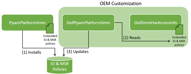
This section explains how IO port and MSR access policies are installed, and then, updated by OEM. The overview is depicted below.
PpamPlatformSmm
- GUID:
91D211BF-37C2-495A-8DF7-9546BD2555C0 - Developer: Intel, customized by OEM
This small SMM module contains and installs the default security policy provided by Intel.
The module runs during the SMM configuration phase, resolves the security policy manipulation API, the gSmmResourceConfigProtocolGuid protocol implemented in PiSmmCpuDxeSmm, and calls it with statically embedded IO and MSR policies.
The statically embedded policies are converted into the following runtime formats through the protocol:
- MSRs: That of the MSR bitmaps (see: “25.6.9 MSR-Bitmap Address” in the Intel SDM).
DgrReleaseSpsenforces the policy by looking up this bitmap on #GP. - IO ports: That of the IO permission bitmap. The processor enforces the policy by using this bitmap as the IO permission bitmap (see: “19.5.2 I/O Permission Bit Map” in the Intel SDM). The IO permission bitmap is an old mechanism in the processors, allowing user-mode code to access IO ports specified by the bitmap.
It is worth noting that the IO port and MSR access policies are allow-list based, reducing the risk of having overly permissive policies.
The policies are customizable by OEMs until the SMM configuration is locked and third-party code starts running. This provides flexibility to OEMs while preventing malicious customization by third-party code. We will take a look at customization by Dell in the OEM customization section.
For the contents of the default policies embedded in this file, refer to the Appendix section.
OEM customization
DellPpamPlatformSmm
- GUID:
3C4B7480-E1D8-4D59-80C1-7307A2B1D666 - Developer: Dell (OEM)
This SMM module updates the default security policy with these by Dell.
This module registers a callback executed right before SMM configuration is locked. The callback resolves Dell’s additional policies in DellSmmHwAccessInfo, then, adds more allowed IO ports and MSRs using the previously mentioned gSmmResourceConfigProtocolGuid protocol.
DellSmmHwAccessInfo
- GUID:
7652F853-6243-4358-2BBD-6F235DCA34AB - Developer: Dell (OEM)
This SMM module embeds and exposes Dell’s additional allowed IO ports and MSRs.
Dell’s policies open access to 114 MSRs and, at most, 7 IO ports in addition to the Intel-provided policies. For the list of them, see the Appendix section.
Debug registers write access policy
Whether writing to debug registers is allowed is ruled by a value pointed by the entry type 0xC of SMM_INFO. This value is hard-coded to disallow access and is neither updated by the patching mechanism nor customizable to OEMs in the analyzed version. The use of debug registers from user-mode SMM modules is most likely allowed only with a debug version for OEMs.
Further research areas
These are potentially interesting areas to further study:
- Access policies for memory and processor saved state access.
- Exploitability of the default and Dell security policies should user-mode SMM be compromised.
Conclusion
In this post, we reviewed the design and implementation of ISRD; the mechanism to deprivilege SMI handlers into user-mode and enforce security policies from kernel-mode. Along the way, we also studied runtime patching, and layouts and customization of the security policies by OEM. Finally, we enumerated the lists of IO ports and MSRs still accessible from the user-mode SMI handlers under Intel’s and Dell’s security policies.
ISRD is beautifully architected by taking advantage of existing processor features. It is relatively straightforward to learn compared with ISSR (which will be discussed in the next post), as almost all aspects of implementations are in either software or well-understood hardware features. If you are interested in low-level platform security, studying it is worth the effort.
Footnotes
*1 (🔙): SMM_SUPOVR_STATE_LOCK (MSR 0x141) is undocumented. It is the implementation of Intel Runtime BIOS Resilience, the hardware enhancement to lock CR0, CR3, and other security sensitive registers even against kernel-mode SMM code.
*2 (🔙): If ISRD is not enabled, the SMM entry point simply JMPs to the user-mode entry point in PiSmmCpuDxeSmm, meaning the same code is executed in kernel-mode.
*3 (🔙): To be precise, if a non continuable exception is raised from user-mode, execution goes back to user-mode and dumps register values before halting the processor. This code also contains an unreachable path that lets user-mode continue execution, which is most likely to help OEMs audit policy violations while developing their SMM modules.
*4 (🔙): The CLI instruction is handled as no-op by the SPS.
Appendix
SMM_INFO patch entry types
Click to expand
Below is dump of the SMM_INFO patch entries on my system with a description of each type. The “Patched” column indicates whether the value is updated at the runtime with the mechanism described above.
Type | Size | Offset | Patched | Description
00   | 04   | 0002   |         | Size of SPS entry point code
01   | 06   | 004B   | Yes     | SMM GDT limit and base
02   | 0A   | 0660   | Yes     | SMM IDT limit and base
03   | 04   | 0086   | Yes     | SMM CR3
05   | 08   | 04BD   | Yes     | SMM_SUPOVR_STATE_LOCK (0x141)
06   | 04   | 0065   | Yes     | SMM Stack pointer
07   | 04   | 0074   | Yes     | SMM Stack size
08   | 04   | 0676   | Yes     |
09   | 04   | 067A   | Yes     |
0A   | 04   | 067E   |         |
0B   | 04   | 0682   |         |
0C   | 01   | 0400   |         | Allow write-access to debug registers
0D   | 01   | 042B   | Yes     |
16   | 08   | 066A   | Yes     | SPS base
17   | 04   | 0672   |         |
80   | 01   | 049A   | Yes     | User-mode enabled
81   | 08   | 04DD   | Yes     | User-mode entry point
82   | 04   | 0492   | Yes     | User-mode stack pointer
83   | 04   | 068E   | Yes     | User-mode stack size
84   | 08   | 0692   | Yes     | User-mode exception handler
85   | 04   | 0474   | Yes     |
86   | 04   | 047B   | Yes     |
91   | 08   | 069A   | Yes     | MSR bitmap address
94   | 08   | 017B   | Yes     | SMM XCR
95   | 08   | 0197   | Yes     | SMM IA32_XSS
FF   | 00   | 0000   |         | End of the list
Default IO port access policy
Click to expand
The following IO ports are allowed to access with the IN, OUT, INS, and OUT instructions from user-mode:
- 0x2e - 0x2f
- 0x4e - 0x4f
- 0x60
- 0x62
- 0x64
- 0x66
- 0x70 - 0x77
- 0x80 - 0x83
- 0xb2 - 0xb3
- 0x2e8 - 0x2ef
- 0x2f8 - 0x2ff
- 0x3e8 - 0x3ef
- 0x3f8 - 0x3ff
- 0x400 - 0x413
- 0xcf9
- 0x1800 - 0x187f
- 0xefa0 - 0xefb7
Default MSR access policy
Click to expand
The following MSRs are allowed to access with the RDMSR and WRMSR instructions from user-mode, unless noted otherwise:
- 1bh - IA32_APIC_BASE
- 35h - MSR_CORE_THREAD_COUNT
- 35h - MSR_CORE_THREAD_COUNT (Hey Intel, you have two of this)
- 3ah - IA32_FEATURE_CONTROL
- 9dh - undocumented (MSR_SMM_PROT_MODE_BASE)
- 9eh - IA32_SMBASE (No
WRMSRallowed) - ceh - MSR_PLATFORM_INFO
- feh - IA32_MTRRCAP
- 110h - undocumented (MSR_PLAT_FRMW_PROT_CTRL)
- 115h - undocumented (MSR_PLAT_FRMW_PROT_TRIG_PARAM)
- 116h - undocumented (MSR_PLAT_FRMW_PROT_TRIGGER)
- 179h - IA32_MCG_CAP
- 17ah - IA32_MCG_STATUS
- 17dh - MSR_SMM_MCA_CAP
- 194h - MSR_MCG_R12
- 19bh - IA32_THERM_INTERRUPT
- 19ch - IA32_THERM_STATUS
- 1a0h - IA32_MISC_ENABLE
- 1a2h - MSR_TEMPERATURE_TARGET
- 1aah - MSR_MISC_PWR_MGMT
- 1adh - MSR_TURBO_RATIO_LIMIT
- 1b1h - IA32_PACKAGE_THERM_STATUS
- 1b2h - IA32_PACKAGE_THERM_INTERRUPT
- 1d9h - IA32_DEBUGCTL
- 1f2h - IA32_SMRR_PHYSBASE
- 1f3h - IA32_SMRR_PHYSMASK
- 1feh - undocumented (MSR_SPCL_CHIPSET_USAGE)
- 4d0h - IA32_MCG_EXT_CTL
- 4e0h - MSR_SMM_FEATURE_CONTROL
- 4e3h - MSR_SMM_BLOCKED
- 606h - MSR_RAPL_POWER_UNIT
- 610h - MSR_PKG_POWER_LIMIT
- 614h - MSR_PKG_POWER_INFO
- 770h - IA32_PM_ENABLE
- 773h - IA32_HWP_INTERRUPT
- 777h - IA32_HWP_STATUS
- 791h - undocumented (R_SA_MSRIO_ADDRESS)
- 802h - IA32_X2APIC_APICID (No
WRMSRallowed) - 830h - IA32_X2APIC_ICR
- 833h - IA32_X2APIC_LVT_THERMAL
Dell’s additional IO port access policy
Click to expand
The following IO ports are additionally allowed to access per Dell’s customization:
- 0x900 - 0x901
- 0x930
- 0x934
- 0xa1
- 0x94e - 0x94f (Optional)
- 0x20 (Optional)
- 0xa0 (Optional)
Dell’s additional MSR access policy
Click to expand
The following MSRs are additionally allowed to access per Dell’s customization:
- 34h - MSR_SMI_COUNT
- 8bh - IA32_BIOS_SIGN_ID
- e2h - MSR_PKG_CST_CONFIG_CONTROL
- 13ah - undocumented (MSR_BOOT_GUARD_SACM_INFO)
- 198h - IA32_PERF_STATUS
- 19ah - IA32_CLOCK_MODULATION
- 1fch - MSR_POWER_CTL
- 200h - IA32_MTRR_PHYSBASE0
- 250h - IA32_MTRR_FIX64K_00000
- 258h - IA32_MTRR_FIX16K_80000
- 259h - IA32_MTRR_FIX16K_A0000
- 268h - IA32_MTRR_FIX4K_C0000
- 280h - IA32_MC0_CTL2
- 281h - IA32_MC1_CTL2
- 282h - IA32_MC2_CTL2
- 283h - ..
- 284h - ..
- 285h - ..
- 286h - ..
- 287h - ..
- 288h - ..
- 289h - ..
- 28ah - ..
- 28bh - ..
- 28ch - ..
- 28dh - ..
- 28eh - ..
- 28fh - ..
- 290h - ..
- 291h - ..
- 292h - ..
- 293h - ..
- 294h - ..
- 295h - ..
- 296h - ..
- 297h - ..
- 298h - ..
- 299h - ..
- 29ah - ..
- 29bh - ..
- 29ch - ..
- 29dh - ..
- 29eh - ..
- 29fh - IA32_MC31_CTL2
- 2ffh - IA32_MTRR_DEF_TYPE
- 3f8h - MSR_PKG_C3_RESIDENCY
- 3f9h - MSR_PKG_C4_RESIDENCY
- 3fah - MSR_PKG_C6_RESIDENCY
- 3fch - MSR_CORE_C3_RESIDENCY
- 3fdh - MSR_CORE_C6_RESIDENCY
- 3feh - MSR_CORE_C7_RESIDENCY
- 400h - IA32_MC0_CTL
- 401h - IA32_MC0_STATUS
- 404h - IA32_MC1_CTL
- 405h - IA32_MC1_STATUS
- 408h - IA32_MC2_CTL
- 409h - IA32_MC2_STATUS
- 40ch - ..
- 40dh - ..
- 410h - ..
- 411h - ..
- 414h - ..
- 415h - ..
- 418h - ..
- 419h - ..
- 41ch - ..
- 41dh - ..
- 420h - ..
- 421h - ..
- 424h - ..
- 425h - ..
- 428h - ..
- 429h - ..
- 42ch - ..
- 42dh - ..
- 430h - ..
- 431h - ..
- 434h - ..
- 435h - ..
- 438h - ..
- 439h - ..
- 43ch - ..
- 43dh - ..
- 440h - ..
- 441h - ..
- 444h - ..
- 445h - ..
- 448h - ..
- 449h - ..
- 44ch - ..
- 44dh - ..
- 450h - ..
- 451h - ..
- 454h - ..
- 455h - ..
- 458h - ..
- 459h - ..
- 45ch - ..
- 45dh - ..
- 460h - ..
- 461h - ..
- 464h - ..
- 465h - ..
- 468h - ..
- 469h - ..
- 46ch - ..
- 46dh - ..
- 470h - IA32_MC28_CTL
- 471h - IA32_MC28_STATUS
- 630h - MSR_PKG_C8_RESIDENCY
- 631h - MSR_PKG_C9_RESIDENCY
- 632h - MSR_PKG_C10_RESIDENCY
- 790h - undocumented (MC_ERR_INJ_LCK)
- 802h - IA32_X2APIC_APICID
Found this post interesting? We offer a training course about the Intel virtualization technology. Check out the course syllabus.