SMM isolation - Security policy reporting (ISSR)
This two-post series details the inner workings of System Management Mode (SMM) isolation on the Intel platform and interaction with Windows.
This post focuses on SMM security policy reporting and interaction with Windows. For SMI deprivileging, see the previous post.
Table of contents👇
Background
To minimize the impact of vulnerabilities in SMM, Intel implemented Intel System Resources Defense (ISRD) where SMM interrupt (SMI) handlers run in user-mode and can access security sensitive resources only when security policies grant it. Intel provides the policies to OEMs and allows them to customize the policies. The previous part of this blog series details ISRD.
With ISRD, the SMM is supposedly secure – but how would one tell if OEM did not install allow-everything™️ policies?
Non-SMM cannot read SMM memory (SMRAM) or tell what security policies are in effect. The SMM needs to provide an interface for non-SMM to expose this information in a secure and trusted manner. Although the traditional way of doing this is to implement an SMI handler, it would be untrusted as ISRD’s threat model assumes SMM modules may be compromised (*1).
To solve this problem, it is necessary that the reporting mechanism cannot be tampered with, or if it can, it is detectable (*2).
Overview of ISSR
Intel System Security Report (ISSR), code-named “Nifty Rock”, is Intel’s solution to this problem, taking the “tampering is detectable” approach. Under the ISSR architecture, an SMM security policy reporting component, called Platform Properties Assessment Module (PPAM), is verified and executed by yet another verified component, called Measured Launch Environment (MLE), while eliminating the risk of being compromised between verification and execution using Intel Trusted Execution Technology (TXT).
The below illustration depicts how each component in the ISSR architecture is verified and executed, from processor microcode to the security policy reporting component on Windows.
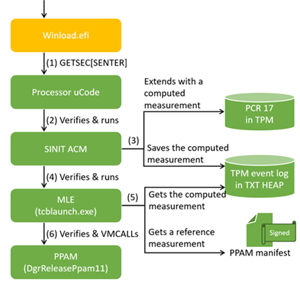
(Green indicates trusted or tamper-detectable components under the ISSR security model.)
- Winload.efi initiates measured launch by executing the
GETSEC[SENTER]instruction. - The processor verifies and executes the SINIT ACM.
- The SINIT ACM measures (ie, hashes) PPAM and saves the measurement (ie, digest) into the TPM event log.
- The SINIT ACM verifies and executes tcblaunch.exe.
- tcblaunch.exe gets the computed measurement from the TPM event log and a reference measurements from a PPAM manifest, and then, verifies both matches.
- tcblaunch.exe hypercalls PPAM and receives security policies.
During these operations, no other code than the above runs, and there is no chance of tampering, thereby achieving trusted reporting from PPAM.
ISSR implementation
Here, we will analyze technologies and components that implement the ISSR architecture (*3). The later Interaction with Windows section will explain how the Windows secure launch process interacts with them.
DgrReleasePpam11
- GUID:
943D4107-5D78-4233-A382-6260062C554C - Developer: Intel
This is the PPAM – the SMM module that exposes an interface to non-SMM to report security policies enforced.
The file is in the SMM Transfer Monitor (STM) format, that is, an SMM module following 0x2000 bytes of the STM_HEADER and other data structures.
This file is loaded into SMRAM and registered as an STM by PpamPlatformSmm (91D211BF-37C2-495A-8DF7-9546BD2555C0) during the SMM configuration phase and executed via two hypercalls from MLE, specifically, tcblaunch.exe on Windows. One of the hypercalls reports the security policies.
The STM was designed to run SMM in guest-mode using VT-x. However, unlike a conventional STM, PPAM does not deprivilege SMM modules since the ISRD architecture achieves it. PPAM is developed as an STM so that it can:
- be measured (ie, hashed) by a trusted component, the SINIT ACM, and
- provide a hypercall-based interface to avoid dependency on SMI
The former addresses the “tampering is detectable” aspect of the ISSR architecture. Let us review how this is achieved in more detail, starting with Intel TXT.
Intel Trusted Execution Technology
(Skip this section if you have a good handle on Intel TXT)
Intel Trusted Execution Technology (TXT) is a set of technologies to establish a dynamic chain of trust.
In short, it allows software to ask a processor to verify the integrity of a specified software and execute it in a trusted way. The main premises and goals are that:
- Processors are difficult to tamper with and can be trusted.
- And thus, software components verified by the processor directly or indirectly can also be trusted, as long as no unverified software runs.
- Achieve this with the shortest chain of trust to minimize the chance of errors and possible known-good states.
(2) is widely implemented as a combination of Intel Boot Guard (or AMD secure boot) and UEFI secure boot. However, it is challenging to do so right and take advantage of it due to the complexity of UEFI and the wide range of components need to be verified.
Instead, TXT starts the chain of trust from an arbitrary moment, hence the “dynamic” chain of trust, and very quickly jumps to a software component that wants a trusted execution environment, achieving both (2) and (3) the above.
TXT does so by resetting a processor to a predefined state with the GETSEC[SENTER] instruction as illustrated below.
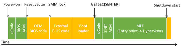
(Green indicates trusted components under the TXT security model.)
The instruction microcode verifies the integrity of a region of memory specified by software and starts executing it if there is no issue. This first piece of software is called SINIT ACM, which will be explained shortly.
It is crucial that after execution of the GETSEC[SENTER] instruction, no unverified software runs until explicitly allowed. All interrupts are disabled, and other processors halt their execution. Thus, even if an SMM module is already tampered with by the time of GETSEC[SENTER], it still cannot impact execution as SMIs are disabled.
More details of the instruction can be found in the “CHAPTER 7 SAFER MODE EXTENSIONS REFERENCE” of Intel SDM, and interaction with other components like SINIT ACM and MLE are in the “Intel® Trusted Execution. Technology (Intel® TXT). Software Development Guide. Measured Launch Environment Developer’s Guide”, which we will refer to as the MLE DG.
SINIT ACM
- GUID:
3FB89FE4-CFC5-4C54-9EEE-E3DF016E3269 - Developer: Intel
It is a blob file containing the first software code executed after GETSEC[SENTER]. The “ACM Header format” section of the MLE DG and “Table 7-6. Register State Initialization After GETSEC[SENTER] and GETSEC[WAKEUP]” of the Intel SDM document the file format and the initial register value, respectively.
SINIT ACM is exclusively 32-bit code and verifies the system configurations to ensure the rest of the process can complete securely. For example, it checks that memory needed for SINIT ACM and MLE are protected from DMA so that DMA cannot influence measured launch. The list of verified things includes but is not limited to PCH registers, TPM, MTRRs, and IOMMU, a total of over 300 checks.
Another important thing the SINIT ACM does for the ISSR architecture is that it measures a registered STM (*4). The measurement is used to extend the PCR 17 and saved to the TPM event logs on a protected region of memory called TXT heap. The latter is critical because it allows MLE to compare it with a reference measurement and verify the integrity of PPAM as we review later.
For more details on the use of TPM and the TPM event logs, see the “1.10 PCR Usage” and “TPM Event Log” sections of MLD DG, respectively.
Once the SINIT ACM completes all verification and measurement, it executes the GETSEC[EXITAC] instruction to indicate the end of SINIT ACM and jumps to the entry point of MLE as specified by software before execution of the GETSEC[SENTER] instruction though TXT heap.
MLE
MLE is a software component whose integrity is measured through the above-explained process. In the case of Windows, tcblaunch.exe is the entry point of MLE.
It is executed from the SINIT ACM with the initial register state documented in the “Table 34. Platform State upon SINIT exit and return to MLE” section of the MLE DG.
MLE is the non-SMM software that talks to PPAM and retrieves security policies enforced by the ISRD architecture. MLE can do this in a trusted way because its integrity is measured, making corruption detectable, and no untrusted code or DMA can interfere with its execution.
Interaction with Windows
To make discussions more concrete, let us analyze how the technologies and components we reviewed fit with the Windows boot process. That is, implementation of System Guard Secure Launch, with a focus on tcblaunch.exe and PPAM interactions.
TXT heap initialization
The secure launch process starts with preparing the TXT heap way before the execution of the GETSEC[SENTER] instruction.
TXT heap is a memory region to pass data between BIOS, OS, SINIT ACM, and MLE. It consists of 4 sets of data produced and consumed by different components. The below diagram shows this relationship.
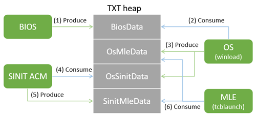
BIOS performs the first phase of heap initialization, specifically:
TxtDxe(FF917E22-A228-448D-BDAA-68EFCCDDA5D3) allocates the heap and initializesBiosData, except ones related to SINIT ACM.PlatformAdvancedDxe(C5046EFD-7BC3-4206-987C-32DA45026E6D) populates the SINIT ACM related part ofBiosDataif SINIT ACM is available.
The next phase of initialization is winload.efi populating OsMleData and OsSinitData parts with the TxtInitializeTxtHeap function.
3 of these 4 data structures have defined formats so a consumer can understand provided data. For example, SINIT ACM can know the entry point of MLE because OsSinitData has an address of the MLE header, which contains the entry point of MLE. Additionally, for each component to be able to find the TXT heap, the address of the heap must be written to the TXT.HEAP.BASE register at physical address 0xfed30300. The below illustrates the chain of data just explained:
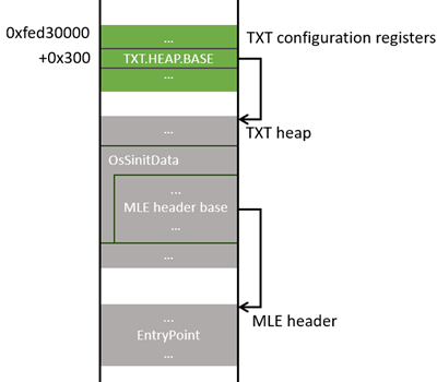
(Green indicates MMIO memory. Gray indicates DRAM memory.)
For more information on TXT heap and TXT registers, see “Intel® TXT Heap Memory” and “Intel® Trusted Execution Technology Configuration Registers” of the MLE DG.
Secure launch
- Key function:
TxtpLaunchMle
After preparing the necessary data structures, winload.efi initiates the measured launch process by executing the GETSEC[SENTER] instruction. On Windows, this process is referred to as “secure launch”.
The true entry point of MLE is mlestartup.exe embedded into tcblaunch.exe. mlestartup.exe can be identified with the UUID 5aac8290-6f47-a774-0f5c-55a2cb51b642 as described in the “Table 3. MLE Header structure” of the MLE DG. Its primary goal is to set up and transition to long-mode and jump to tcblaunch.exe.
The “The Secure Launch” section of the Windows Internals part 2 explains more about the process. We will focus on the interactions with PPAM.
PPAM integrity check
- Key function:
BlpTxtValidatePpamBinaryManifest
One of the first steps tcblaunch.exe does with PPAM is to verify the integrity of it on memory. tcblaunch.exe does this by comparing the measurement of PPAM computed by the SINIT ACM and a reference measurement.
The computed measurement is extracted from the TPM event log through the TXT heap (*5). The reference measurement is taken from the PPAM manifest as explained next. If the digests match, tcblaunch.exe proceeds with interacting with PPAM. If not, it skips that and marks the environment as unsafe.
DgrReleasePpam11Manifest
- GUID:
6C8FAEE0-6521-477A-83BF-0D6598DD28A2 - Developer: Intel
This is the PPAM manifest containing the reference measurement of the DgrReleasePpam11 file.
It is an x509 certificate in the DER format following a 12-byte custom header. After removing the header, the raw data can be dumped with openssl.
$ openssl asn1parse -in DgrReleasePpam11Manifest.p7b -inform DER
...
   61:d=5  hl=3 l= 244 prim: OCTET STRING      [HEX DUMP]:5050414D5F4D414E49464553540001007DA5AE5A7E1CEE488EDB5D2831F78CEE00000000BA2D1160BA2D116000000000000000000000000000000000000000000000000091081B95D3123977DC1DEA8AFEFFA9F40A72E50F94E7A7AE1B780EFAD035509A000000000000000000000000000000000000000000000000000000000000000000000000000000000000000000000000000000000000000000000000000000000000000000000000000000000000000000000000000000000000000000000000000000000000000000000000000000000000000000000000000000000000000000000000000000000000000000000000
...
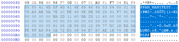
Notice that the last non-zero data within the above output and image is the SHA256 digest of the DgrReleasePpam11 file.
$ sha256sum DgrReleasePpam11_body.bin
91081b95d3123977dc1dea8afeffa9f40a72e50f94e7a7ae1b780efad035509a  DgrReleasePpam11_body.bin
During the SMM configuration phase, this manifest file is copied outside SMRAM as a configuration table by PpamPlatformSmm and becomes available for checking PPAM integrity. Although the PPAM manifest is exposed to non-SMM, tampering with it would be detectable as it is signed.
PPAM invocation
- Key function:
BlpTxtValidateSmmConfiguration
Once the integrity of the PPAM on memory is verified, tcblaunch.exe enters VMX root-operation by executing the VMXON instruction in the BlpTxtPpamVmxInit function. It is possible to execute this instruction since Windows is still in an early boot phase, and Windows Hypervisor has not started yet.
Then, tcblaunch.exe executes the VMCALL instruction a few times to call PPAM hypercalls (*6). This hypercall interface is as follows:
Input:
- eax = Hypercall number
- ebx:ecx = Physical address of the buffer descriptor as below
Output:
- eax = 0 if successful. 0x8xxx_xxxx if error
struct PPAM_HYPERCALL_BUFFER_DESCRIPTOR {
  uint64_t BufferPhysicalAddress;

  // For input, the size of `BufferPhysicalAddress`.
  // For output, it may be updated with the required size.
  uint32_t BufferSize;
};
There are two hypercalls, 0x10009 and 0x1000A, and each of them is called twice: first to get the required buffer size, and then, to get actual data.
On hypercall, PPAM checks that the system is in MLE by checking the TXT.STS register. At the end of hypercall handling, PPAM executes the VMLANCH or VMRESUME instruction with the “deactivate dual-monitor treatment” VM-entry control set to 1. This prevents PPAM from behaving as a conventional STM and causing any other VM-exits besides this hypercall interface.
Hypercall 0x10009
This hypercall provides information about PPAM itself and is only used to decide whether the other hypercall should be called. The result is based on the header data prepended in the DgrReleasePpam11 file, and thus, static.
Hypercall 0x1000A
This hypercall returns the effective security policies, which includes:
- 0x100 - Memory ranges
- 0x101 - IO ports
- 0x102 - MSRs
- 0x103 - Protection on SMM state save
- 0x201 - Lock of SMM configuration
The formats of the IO ports and MSR access policies returned by PPAM are that of the IO permission bitmap and MSR bitmap, respectively. PPAM resolves the IO ports bitmap from the SMM TSS and the MSR bitmap through the SMM_INFO data structure, which is analyzed in the previous post.
Policy evaluation
- Key function:
BlpSmmTxtEvaluatePolicy
The policies returned by PPAM are evaluated and translated into an SMM isolation level, ranging from 3 (best), 2, 1, or disabled/error (worst). The requirements for IO ports and MSRs to be qualified for each level are listed in the Appendix section.
The SMM isolation level is further mapped into one of the following integers, which is extended to PCR 20 and saved into the TPM event log as an event ID 0x000c0002 (SIPAEVENT_DRTM_SMM_LEVEL).
| Level | Reported as |
|---|---|
| 3 | 0x1e (30) |
| 2 | 0x14 (20) |
| 1 | 0xa (10) |
| Disabled/Error | 0xff |
Here is a dump of the event log taken on my system, indicating the SMM isolation level being 3 (0x1e).
<EV_Event_Tag PCR="20" EventDigest="ec16c02772e4aa64c15182d222452bc3f848f0cbd69325855bbfe04a98db3dfa" Size="9">
  <SipaEvent Type="0x000c0002" Size="1">
    1e
    <!-- . -->
  </SipaEvent>
</EV_Event_Tag>
Extending the PCR implies that even if an attacker prevents registration of PPAM by exploiting SMM configuration phase code as explained by the Binary team, it will be visible from an OS and security software. Though, worth noting that being visible does not mean someone or something watches out for anomalies and reacts to them. Researching the actual impact of having unexpected PCR 17, 20, or a low SMM isolation level under bare Windows and EDR software is left to readers.
Conclusion
In this post, we analyzed the implementation of ISSR and how Windows interacted with it to receive the SMM security policies from PPAM by establishing the trusted execution environment. Technologies and components we reviewed include PPAM, PPAM manifest, Intel TXT, TXT heap, SNIT ACM, tcblaunch, hypercalls, SMM isolation level, and TPM event logs. We also identified IO ports and MSRs deemed to have security implications from Windows’ perspective based on the requirements for isolation levels.
Although understanding the threat model and technology stack of ISSR is challenging, I greatly enjoyed solving the puzzle of how each piece builds up the ISSR architecture together. Also, while we did not discuss any new security issues, learning modern security mechanisms is still a great way to think through possible attack vectors and is recommended for security minded folks.
 (Your holiday trip is canceled, human.)
Footnotes
*1 (🔙): The other reason SMI would not work is that such SMM modules are not measured during the measured launch, and thus, no way to verify its identity and integrity in the first place.
*2 (🔙): And any reasonably complex software systems can be tampered with.
*3 (🔙): Do not confuse ISSR (PPAM) with a mechanism to deprivilege SMM. Some articles mix them up. They are strongly related but well-isolated technologies.
*4 (🔙): I am unclear on what mechanism allows SINIT ACM to access SMRAM. My guess is that this is one of the things allowed during the authenticated code execution mode, but it does not appear to be documented.
*5 (🔙): On Windows, TPM event logs are eventually saved on C:\Windows\Logs\MeasuredBoot\ and can be queried through the TPM Base Services. This log is called Windows Boot Configuration Logs (WBCL) or TCG event logs in the Windows nomenclature and is parsable with API prefixed with Wbcl. See the TSS.MSR repository for examples. Here is the output of the modified version of the log parser on my system, showing the digest of PPAM in the event 0x0000040E (SIPAEV_TXT_STM_HASH)
<TCGEvent Type="0000040e" PCR="17" Digest="91081b95d3123977dc1dea8afeffa9f40a72e50f94e7a7ae1b780efad035509a" Size="0"/>
Notice this 9108... matches with the SHA256 digest of the PPAM file above. By parsing them, third-party software can verify state of ISRD and ISSR, for example.
*6 (🔙): You might have wondered when the VMLAUNCH instruction ran before the VMCALL instruction. It was not. Once the STM is registered, the VMCALL instruction during VMX root-operation causes a transition to the STM entry point as “SMM VM Exits”. For more information, see “32.15.6 Activating the Dual-Monitor Treatment” in the Intel SDM.
Appendix
SMM isolation level requirements
Click to expand
The below lists IO ports that cannot be accessible to be entitled to each isolation level. It would be interesting to take a closer look to see why some MSRs are listed as requirements while others are not.
Level 1:
- No requirement
Level 2:
- 0xcf8 - 0cfb
- 0xcfc - 0cff
Level 3:
- Same as level 2
The below lists MSRs that cannot be accessible to be entitled to each isolation level. Requirements are different for AMD and Intel systems. The list shown here is for Intel.
Level 1
- No requirement
Level 2
- e4h - MSR_PMG_IO_CAPTURE_BASE
- 600h - IA32_DS_AREA
- 652h - MSR_PKG_HDC_CONFIG
- 653h - MSR_CORE_HDC_RESIDENCY
- 655h - MSR_PKG_HDC_SHALLOW_RESIDENCY
- 656h - MSR_PKG_HDC_DEEP_RESIDENCY
- 658h - MSR_WEIGHTED_CORE_C0
- 700h - MSR_UNC_CBO_0_PERFEVTSEL0
- 701h - MSR_UNC_CBO_0_PERFEVTSEL1
- 706h - MSR_UNC_CBO_0_PERFCTR0
- 707h - MSR_UNC_CBO_0_PERFCTR1
- 710h - MSR_UNC_CBO_1_PERFEVTSEL0
- 711h - MSR_UNC_CBO_1_PERFEVTSEL1
- 716h - MSR_UNC_CBO_1_PERFCTR0
- 717h - MSR_UNC_CBO_1_PERFCTR1
- 720h - MSR_UNC_CBO_2_PERFEVTSEL0
- 721h - MSR_UNC_CBO_2_PERFEVTSEL1
- 726h - MSR_UNC_CBO_2_PERFCTR0
- 727h - MSR_UNC_CBO_2_PERFCTR1
- 730h - MSR_UNC_CBO_3_PERFEVTSEL0
- 731h - MSR_UNC_CBO_3_PERFEVTSEL1
- 736h - MSR_UNC_CBO_3_PERFCTR0
- 737h - MSR_UNC_CBO_3_PERFCTR1
Level 3
- All of the above and
- 570h - IA32_RTIT_CTL
Further learning resources
Click to expand
- TXT
- Intel SDM, “CHAPTER 7 SAFER MODE EXTENSIONS REFERENCE”
- Intel® Trusted Execution. Technology (Intel® TXT). Software Development Guide. Measured Launch Environment Developer’s Guide
- Intel Trusted Execution Technology for Server Platforms: A Guide to More Secure Datacenters
- Building Secure Firmware: Armoring the Foundation of the Platform
- Attacking Intel® Trusted Execution Technology
- TPM
- A Practical Guide to TPM 2.0: Using the Trusted Platform Module in the New Age of Security
- TCG PC Client Platform Firmware Profile Specification
- “10 Event Logging” for event logs.
- STM
- ISRD/ISSR
- Intel® Hardware Shield: Trustworthy SMM on the Intel vPro® Platform
- System Management Mode deep dive: How SMM isolation hardens the platform
- Intel® Hardware Shield – Below-the-OS Security
- Force firmware code to be measured and attested by Secure Launch on Windows 10
- Breaking Firmware Trust From Pre-EFI: Exploiting Early Boot Phases
Found this post interesting? We offer a training course about the Intel virtualization technology. Check out the course syllabus.